Week 2: Rotoscoping
Rotoscoping is an animation technique introduced by Max Fleischer in 1915. This technique enabled animators to draw figures frame by frame over filmed action. this resulted in more of a life like movement. Rotoscoping has been used in the VFX industry to animate characters by Tracing, to enhance the objects e.g. Light Sabers in Star Wars and also to remove objects from a scene like wires. A good example of Rotoscoping in the animation industry is the tracing of Marge Champion for Snow White.
Nuke: Project Settings
To open up the project setting, we need to hover the mouse over the Node Graph and press S on the key board.
In the project settings window, we can select the fps which is to be set at 25 which is the standard UK TV setting as well.
The Full size format option is where we can select the size of the screen which would mostly be kept at HD 1080

Setting the Project Directory:
To set up the Directory for our project we first need to click on the Black folder Box under project settings:
Then we navigate our project folder in this case it will be:/Users/21349121/Desktop/Nuke_Roto_Basic/
Next we need to open up the File. this can be done by hovering the mouse on the Node graph and pressing R on keyboard. the directory path to select the file in this case is:
/Users/21349121/Desktop/Nuke_Roto_Basic/SHOTS/B001_BEV_355/RAW/i_B001_BEV_355/2240x960/B001_BEV_355.####.dpx
Pressing R will show us the following window which has a set Original Range starting at 1001 and a set Format:

Saving:
In order to save the progress we click on file at the top and then Save Comp As. Next we need to navigate to the right path. in this case,/Users/21349121/Desktop/Nuke_Roto_Basic/SCRIPTS/DATA/Project_directory_test01_v001
Working on the Project:
On important point before working on the project is to delete the Path in the File section as this will enables us to move between different machines:

In order to view the sequence in the viewer, we need to click on the file and press 1, this is all done on the Node Graph.

Hero Frame:
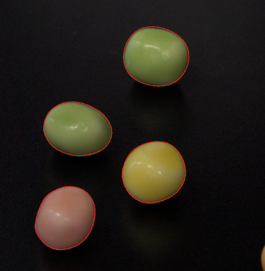
Hero frame is a frame where there is least motion blur and it is the sharpest frame in the sequence. this will all us to use the Rotoscope technique smoothly. The Rotoscoping will always be done around the sharpest frame. In the following clip the hero Frame will be the Yellow bean in the middle as there is not a lot of movement and blur. the frame is sharp as well.
Rotoscoping in Nuke:
In order to use the Rotoscoping technique on a sequence we will hover the mouse in the Node Graph area and press O on the keyboard. this will give us the roto1 node in the Node Graph.
We also need to create a copy node which will let us work on a new layer of the original sequence. This node can be created by hovering the mouse in the Node Graph area and pressing K on the keyboard. this will give us the copy1 node in the Node Graph. Shortcuts can be set on these nodes by selecting each one and giving them a number .e.g. Key 1 for Roto1, Key 2 for Copy1.
The Copy node will have two pipelines, A and B. Pipeline A needs to be connected to Roto1 node and B to the original sequence.

Creating overlays:
To create overlays on the sequence which can then be used for Rotoscoping, we use different tools. These tools appear on the top left of the screen in the viewer.

We can use these tools to create overlays on the sequences. This overlay can then be used to create different effect like glow, blur etc.


A Node Tree:

Working on the Film Sequence:
For Rotoscoping, we need to adjust the overlays created frame by frame. this can be done by using the different tools mentioned above. this would look something like follows:


Now as we can see in the video below, We have singled out the two building tops using the tools. Now these singled out building tops and be edited with and can have effect put various effects on them.
Week 3: Advanced Rotoscoping Exercise
For this session, we looked at taking the Rotoscoping technique further. Moving on from more static clip of the beans last week, we are now using the clip that shows moving fingers. On this moving fingers clip we are trying to apply the rotoscoping technique.
In order to create the rotoscope, we use the Spline tools. the best one to use for this kind of exercise is Bspline which creates shapes that come in handy when putting overlays in fingers.
We also need to make sure that not too many points as it will affect the accuracy of the Rotoscoping technique.

It is also handy to use the in and out from the drop down in the node graph to work on specific key frames.

Using the matte and overlay on and off helps a lot as well this outlines and adds a coloured shadow on the clips being worked on for rotoscoping. this makes the whole procedure a lot easier. to do this we need to hover the mouse in the Node Graph and press M on keyboard for Matte and Q from the overlay on/off.


Advanced Rotoscoping: Blur
One of handy tools when doing Rotoscoping is Blur. This is used when there is already blur in the default clip. this tool helps Nuke to mimic the Blur and put it on the edited clip. to activate the blur on one of the overlay splines, we need to navigate to the properties on the right and go to the Roto properties. There we will have three blurred lines. once we click on that, the blur will be activated. we can also play around with the blur in the motion Blur tab.

The Blur would look something like the following images when activated:


Some of the tips for Rotoscoping technique. When selecting a pint on the Spline, press Z to smoothen the overlay. It also gives you access to two handles that can be moved around individually or simultaneously to create a smooth overlay shape.
Overlapping shapes gives more control when it comes to Rotoscoping.
Using Cmd+left and right arrows, we can select key frames. this gives us a control over the clip and we can move around in the clip to see how well the overlays has been created.
Controlling the Pivot points can give us more control.
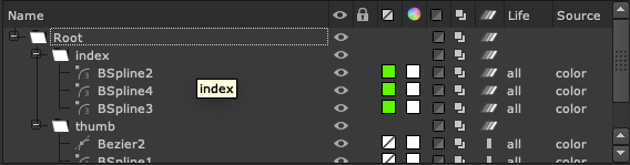
We can also change the colour of the Splines which can help us differentiate between different parts of the clip we are working on .e.g thumb and Index finger. In the following picture I have turned the Splines into green.
We can get this done by clicking in the Roto properties and clink on the Box with a Line

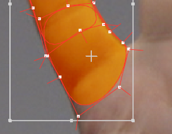
We can also create Grade overlay on the clip. We can do this by hovering the mouse in the Node Graph and press G on the Keyboard it will create a Grade Node. Put it under the Copy Node. then we can connect the Pipeline to the Roto Node. In the following picture I have selected the grade colour to be Orange.


Creating Folders:
We can also create folders for each Splines and put the dedicated Splines into that folder. for todays session we worked on the thumb and the Index finger. For that we created two folders namely Thumb and Index. then we put the Splines in it. This gives us more control on selecting the correct Splines when it comes to Rotoscoping. To do that we go to the Roto properties - Name - then click + sign. this will create a new folder that we can rename.

Advanced Rotoscoping: Clips
Using all the techniques mentioned above and taught to us today, I have been able to do the Rotoscoping as following:
Week 4: Basic Keying
For todays session we looked at the basic keying techniques that we can use in Nuke. Keying is a good technique when it comes to Roto complex shapes like animals and Humans. This is done by generating an alpha channel from the footage.
Luminance Keying:
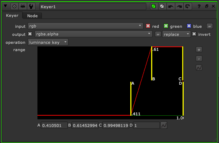
The luminance keying is a technique used in Nuke to get the alpha frame. This alpha channel will separate the white (1) and black (0) in the picture and make it easier to Roto. An example is an exercise we did today in class:


The point of the exercise was to use the Luminance node and Rotoscoping to copy the sky from Pic 1 to Pic 2. The luminance node shows the alpha channel and makes it easier to roto .e.g: pressing A on keyboard to get to Aplha Channel.

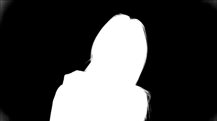
Using the Luminance node, we can change the values and separate the solid white from the black that needs to be taken out. In order to do this we go to the Luminace Keyer mode properties and play around with the setting till we get the required setting. We need to make sure the invert options is selected in the Keyer properties. By selecting the following properties, I got the image shown below.


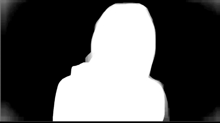
Next we will Roto the Image with the help of adjusted Luminace and the Alpha Channel.

The node tree for the Exercise looks like the following:

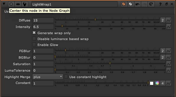
As seen above we have a Stencil Merge which can be used to take out any unwanted scene from the image. Of course this will be taken out after Rotosoping the area. next node is the Lightwrap node which helps with the intensity and the diffuse of the edges e.g.
After all the procedure is followed correctly we will get the following image with a new sky.

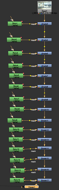
Next we were asked to following the same technique using the same nodes and method for a second exercise. the folowing is the Node tree and the images of the changed sky.


Green Screen Keying:
For this exercise we downloaded an Image sequence and a background image. The purpose of the exercise is to replace the green screen in the Image sequence to the background provided. following are the raw unedited Files:


To start off, we would use the Keylight node. then we will go to the alpha channel and start keying the green. we will select the color picker to do this. this will be in the Keylight node properties in front of Screen Color. This will give us the following red and black cursor to work with.


The first Keying will give us the following result which can be seen in an alpha channel.

To get the Alpha channel white and black to be more solid we will use another Keylight node and call it the Garbage node. this will help us get the solid black and white and also take away the noise in the background to some extent.
Next up is the filter erode node which helps us get back the finer details like the hair back as it might be a little blur using the Keylight nodes. we will then merge the nodes to get a clearer cut out picture with the fine details like the hair intact.

Using merge node to combine all the Keylight nodes and the Filter Erode node gives us the following image, in alpha channel.

Following is the image sequence I was able to achieve after Keylighting and rotoscoping. I also used the grade node to add more brightness to the image in order to match it with the back ground. I have compared the grade and no grade in the following sequence.
Without Grade
With Grade
Week 5: Green Screen Studio Session
For week 6 session we looked at some advanced keying techniques that help when it comes to green screen. First we attended a session in the Green Screen studio with Naman Ali, who explained in detail who to get the best result for keying in green screen and what tools to use to achieve those results.
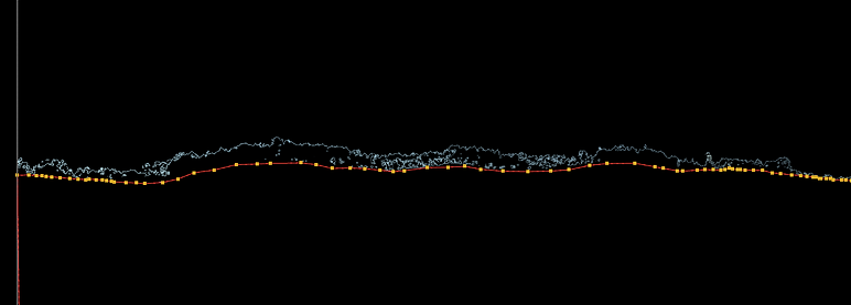
First we were told about the waveform which enables us to see how much exposure and lunar to muse when it comes to lighting the green screen scene. there are two main objects that needs to be lighted up orrectly .i.e. the green screen itself and the talent (Actors). Talking about the waveform, we need to make sure its read from left to right. Bright lighting will give us a high trace on the waveform through which we can tell if the Green Screen or the talent is too bright or too dark. If this is the case, we can then control the aperture from the camera to adjust and get the required result. the Waveform scales from 0 - 100. The best result depending on this Waveform should be between 50 -70 fro the green screen and 70 - 75 for the talent (Actors). this will give us good colour information to work with. We always have to make sure the Green Screen and the Actor are lit separately of course with help of Waveform as mentioned.
Next tool is the Vector scope which allows us to see the intensity and uniformity of the colour in the scene. We were shown a colour chip which is used to detect the colours for green screen. when using the vector Scope for the Green Screen, we need to make sure the scope has a narrow line with a thick blob at the end. this shows the uniformity of the colour of the Green Screen. Having this result will allow for better Keying in software like Nuke. We can also filter the light to green ignorer to get the best results.

Nuke: Advanced Keying

In the Keying session with James, we downloaded the image from the famous movie, Alice Adventure in wonderland. This image had many shades of green in the Green Screen in the background. The objective was to key certain areas using the keylight nodes and get a good result painting the details like hair and laces up the arm.
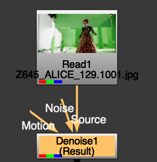
To start off, we needed to first check the image for any grain. The best way to do this is by going to the Blue channel in the viewer and looking for any grains on the image. As the picture below shows, there was grain in the image and in order to eliminate that we used the Denoise node. this was done by putting the Denise node under the Image and connecting the source pipeline to the Image.


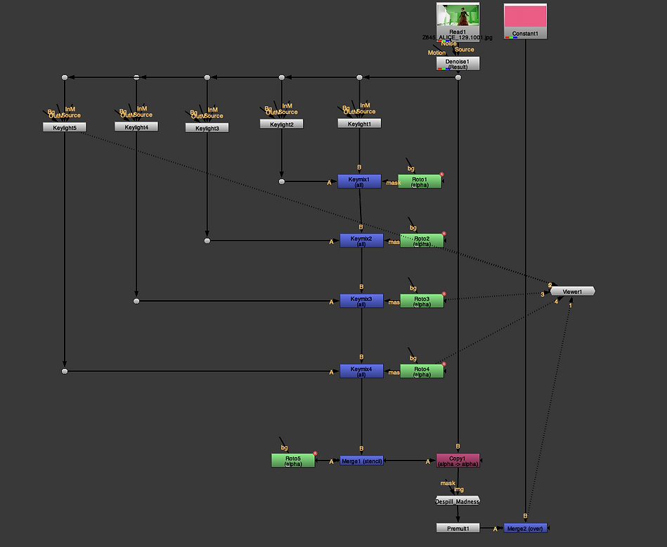
Next we had to key the different part of the images. This will be done by adding the KeyLight node. In the following image we can seethe nodes I have used. First as mentioned on top, we use the Denoise to get rid of the grain. Then we create multiple key light nodes. Using these key light nodes we scan the area and get the green screen keys. In this scenario we were focusing on the left arm of the lady in scene. so we created separate keylights around the lady's arm. following image shows how we have mixed the different key lights into a keymix. So the idea is to merge two key light into one keymix. We can then mask the rotes over these Keymixes to get the Rotoscoped out parts around the arm.

Next, after we have rotoed out the parts we need we can go to alpha cannel and take out the background. so we will have to Roto the background as well. we can then use a different image to replace the back ground. in the following image we can see the background being rotoed out of the scene.

In the following images, for the background I put up a constant node and put different colours (Pink, Red). this is after using all the required nodes. One of a very good node to use is Despill_Madness. this is to be used when we can see green reflection from the green screen.


Week 6: Tracking in Nuke
For this session, we learnt about tracking in Nuke. This is used to track particular area of the scene and keep it in the desired part. We have used different tracking techniques .e.g Nuke tracker and Planar tracker. We can use the normal Nuke tracker by creating a Tracker node. to add a tracker Cross Hair on the viewer (Image Sequence) we can either click on the add track button which is in the Tracker node properties. the following image show the tracker node properties and where to click.

Next we will control the added cross hair and get the required area in the Tracking area. A key point to remember is always change the size format according to the image sequence. after sleeting the area for tracking we click on the play button in the viewer. we also need to make sure to get the Hero Frame to start the tracking with. Following images show the steps to be taken to achieve a track.


Next we will go to the Transafrom on the Tracker properties tab and select match-move 1-pt for transform and reference frame needs to be the hero Frame, which also gives an option to set to current frame.

For our next task, we used the same technique of the tracking but this time using two trackers. The reason for using two trackers is for the image sequences that involve rotation. in these scenarios we will create two tracker nodes and made sure it as parallel when selecting the areas. Both of the tracks we show up on the tracker node properties and we need to make sure we select the transform (T) and scale (S) for both of the tracks. We then roto out an area and connect it to the tracker which goes into a copy node to show us the desired result. the following image shows all the steps that need to be taken and also the Node tree.


Following are the videos with and without the Tracker
For the next task we used the Planar Tracker Technique. for this technique we first found out the hero Fram which was 1094. On this Frame we focused on tracking the wind screen of the car, so we created a Roto around the windscreen.

Then we select the rotoed shape and right click Planar-track this shape (bkwd) this will back track the rotoed out area. Key point, the reason of selecting back track planar track is because our hero frame is right at the end of the image sequence.

This step will track the screen backwards but we still need to do more. next up, we click on the small icon next to the PlanarTrackLayer1 in the viewer and from the drop down select Cornerpin2D (absolute, Baked). this will create an additional node in the Node graph. Next we double click on the Node and go to the properties. in the properties we need to select the From TAB and click on Copy 'to' to get all the values from the Planar used. then we click on the small icons infant of each value and select no animation.


Next we create another roto node and roto out the shape of the screen. then we connect this Roto with the CornerPin2D1 Node and create and copy node. Then we connect the copy node B pipe to the main image and A pipe to the CornerPin node which is connected to the Roto node. The following image is of the Node tree after all the steps have been followed correctly and we have the final Image sequence as well.

Week 8: Colour and Grading

Using the Colour and grading techniques taught in the session, I have been able to achieve the result in the picture above. I have used the keyed grader to highlight the edges of the two buildings and the statue. I have also been using the grade node to do colour correction and match the objects to the surroundings. following is the image zoomed in to see the result clearly.


To get the Colour wheel and adjust the images' colour according to the surroundings. we create a graph node and then go to the properties. in the properties we hold CMD and click on the colour wheel next to the multiply option. this will bring up the options we can see in a picture on the right hand side. we then then adjust the Green Blue and Red values to get the desired result, as it appears on the image above. I followed the same procedure for all the objects put in the scene.

I also added a blur node to bring down the sharpness of the objects and make them fit more realistically in the scene.

To get the highlights on the edges of the buildings to reflect the sun, I added a keyed node and played around with the options. we need to go to the Luminance channel in order to get the desired effect. once we are happy with how much effect we need on the edges, we just connect it to the keyer to the node tree and also add the a new node (grade) to the tree. we then connect the keyer to the grade node in the tree and adjust the multiply in the grade node. in the following image I have enhanced the multiply to show how the edges can be lit up.
In the image on the right I have purposely highlighted the edges of the statue and the small building to be a bit bright to show how the keyer node works together with the grade node. we can see the edges of the statue and the small building reflecting the light of the sun, which was not present in the actual scene.

We also did some additional exercises in the class to get use to the grade nodes. in the image below, I have used the Grade node together with the Roto node to change the colour of each window in the scene. I have also included the Node tree for this exercise.
I have included the node trees for all the objects below:


In the exercise below we have tried and matched the lady in scene to her surroundings. as we can see the surroundings are bright so made the lady in the scene brighter using the Luma Grade and saturation. In the images below I have tried to match the lady to her surroundings.


Week 9: Cleanup and Patch repair
In the session today we learnt about how to get rid of markers and patches especially for the green screen. The nodes that we worked with today are Rotopaint and tracker for the first exercise. First we bring in the rotopaint node and checked all the brushes that are available. The brushes we worked with are Brush, Erase, Clone and Reveal.


The Brush tool allow us to paint over the image and the erase tool helps us erase anything we have painted using the brush tool. these two are pretty straight forward and simple to use. something to keep in mind is that we can use the CMD key on the keyboard to increase and decrease the seize of the brushes. We can also use the adjust the hardness, opacity and colour from the top tab in the viewer. In the images below I have used the brush and Erase tool on a Rotoed out section in the image (using the ROTO NODE OBV).

Next we moved on to using the Reveal Brush. This brush helps reveal what's in the background. To show this we added two backgrounds to the Node tree as BG1 and BG2. Then selecting the bg 1 and 2 from top we used the reveal brush to see the following results.


Next up was the exercise to remove the markers from the following image sequence. The main idea was to remove the yellow markers from the screen. This was done using the rotopaint and the tracker nodes.

First step is to use the Clone brush to get the key from the surrounding are of the marker. the Clone brush acts as a duplicate of the focus area to be applied to the desired area.

Then we track the first frame (the marker we want to get rid of) which will be applied to the rest of the sequence together with using the RotoPaint node Clone Brush. In the clone brush we have to make sure that the Life has been selected to all not to the Frame where the clone has been done on. This can be seen on the image above on the right. to apply the Clone brush to the sequence that has been tracked, which just copy the Translate x, y and the centre x, y values from tracker to Rotopaint. This step I have shown on the image below. we can follow the same steps by creating more tracks and clones but keeping the same Rotopaint node.


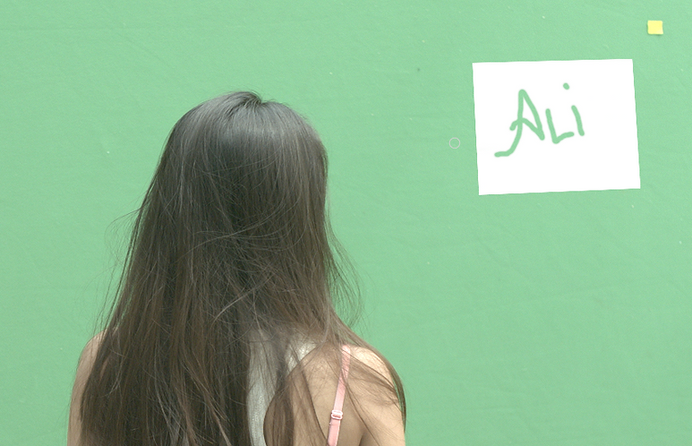
Using the techniques learned, I was able to achieve the following results. I have been able to get rid of the two markers in front of the lady in the image sequence.
Next up we did an exercise where we were to take a certain part of the image sequence out and replace it with the background. in details we were to take an actor out of the scene. I have put the Node tree for this below and I will be explaining what affects these nodes had on the Film sequence.

For the first part we put a Framehold node on the image sequence. this Froze the image sequence as we needed to find a hero frame where we could get a clear background. for the framehold we sleceted frame 1100 and made it the hero frame. Then we rotoed out that particular part of the sequence and put a blur node on it to blend it well in the rest of the image sequence. So in order to bring the roteoed out area to the rest of the sequence we used a copy node and a premult node.

Next we put a denoise node to get rid of any grain on the image. Now as we had changed the rotoed image and we had to match the grain of that rotoed out area with the remaning image sequence. we used the Grain node. this helps us compare and match the grain levels of the rotoed area and the rest of the image sequence. this can be done by pressing W on keyboard while having the cursor in the viewer. this gives us a chance to match the grain using the Red, Green and blue channels.

Below we can see a comparison of how grain works and how it looks after being matched to the rest of the image sequence.


Then we used the multiply node to connect the two pipe lines we have been working on and to also apply the rotoed frame till the two women walk in the rotoed out area. Below we can see the final result of today's exercise.
Week 10: Complex Cleanup
In today's session, we learned a few more techniques for clean up and practices the techniques learned last week for Clean up in Nuke. We worked on two image sequences today and the objective was the same as last week which is to remove the unwanted objects from the image sequence. First we worked with a sequence involving a crowd gathered in a town hall, the objective as to remove the crowd from the sequence. we can see the Stock image sequence below. I will be explaining the nodes and approach we took to remove the crowd.
At first, we took the hero Frame which was at frame 1100. This was our first frame and i have noticed that taking the hero frame from the center of the image sequence counts as this frame will stay there from the start till the end. this time we took the center as the floor which will later be replaced and put where we have the crowd standing. in the image below we can see the hero frame I used.

Next I started working on the node tree. First I created a Roto shape around the area in the image above and then selected the rotoed out area and pressed right click. this gave me the option to fwd tract the image sequence. after wards I went to the top panned and selected the screen icon to baked relative which gave me a Corner Pin node. Now this node has all the tracking data we will be needing further to replace with the crowd location.
Next up I used the rotopaint node to clone out the crowd by using the surrounding environment so I used clone brush tool to replace the crowd with the court yard floor. after completing this i used the framehold node will hold the area using the rotopaint and keep it intact while the sequence plays. Next I used the Roto node to roto out the area I want to apply the frame hold and the Rotopaint to which is obviously the area where the crowd is standing. I also put a blur node to blend the roto well within the sequence. Then we used a Cop node to cross the rotoed out area and the rotopaint and framehold nodes. Next I applied a grade node as the area we are replacing the crowd with is under a shadow. the grade node helped me darken the newly introduced area to get the desired affect. at the end I copied the cornerpin data and just put it before the merge node in the A pipeline so that the tracking data can be applied to the patch we have worked with. we can see the result in the following picture. I have also included the node tree for this exercise below.

For the next exercise in today's session we were to used the same techniques we learnt and get rid of a boat in the following image sequence. I have first put the Stock image sequence below.
Using the techniques learned, we removed the Blue boat and the rope attached to the rock from the image sequqnce. For this exercise we also used the transform node to move the rotoed out water we used to replace the boat with. This took several areas of water being rotoed out and replaced with the boat. In the video below I have shown my first few attempts of doing this before completely replacing the blue boat with water.. Bearing in mind we approached this exercise in exactly the similar way the we did with the exercise with crowd .i.e tracking, baked relative corner pin etc.
In the video above we can see only the front of the boat has been replaced as of yet. I repeated the procedure to completely replace the boat with water and we can see the result below in the video. I have also included the initial and the final node tree.


Week 11: Advanced Cleanup
In today's session, we repeated the techniques we have learned previously in all our nuke sessions before. We worked on a single image sequence this time which included a box logo and a shadow. The main objective was to get rid of the logo on the box and recreate the show on the box. Below is the video we can see which was to be worked on.
In the image sequence above we removed the logo and also replaced the original shadow of the the boys arm with same grade nodes. To start the exercise we use the roto node to create a shape around the logo on the box. now we will use the fwd track and get the tracking data which will used later on. Next we use the frame hold node and freeze the Fram to 1040 which is our hero frame. we then add the Rotopaint node on this frame and use the clone tool to get the logo removed from the box. Afterwards as we have to get rid of the logo through out the image sequence we will use a copy node and a roto node. after this we used the grade node to arrange the luminance, rightness and the colour of the image. the three node were applied to the top corner, bottom and to the box overall. We also put the blur nodes on the grade so that the changes blend in well with the rest of the image. I have put the image of the node tree I have got so far.

Next up we used the cornerPIN node that we got earlier from the track and put it in the node tree. Then we used the grade nodes again to mimic the shadow of the arm on the box. this was done by using the roto node. we used the roto to mimic the shadow of the boys arm. as only the shadow was needed after wards, we used the premult and then a stencil merge together with a roto shape. the blend nodes were applied on the merge to get the required shapes. Then we finally used the merge node to combine the patches with the original image sequence. Below I'm showing the node tree for the procedure mentioned above and the final image sequence after following the correct procedure for this exercise.

Final Node Tree:

Final Image sequnce:
Week 12: Nuke Recap
This weeks session was about recapping the techniques we have learnt so far for Nuke. We started with a familiar exercise which involved removing a logo from a box and this time adding a new logo on the box. Below I'm showing the original image sequence that we worked on today.
To start off the exercise we got the frame hold node and put the hero frame to be 1001. Next up we added the Rotopaint Node above the Framehold Node. Next up we brought in a Copy node and a Roto Node and drew a shape around the logo on the box. Then we put in a Premult node to Isolate the shape and next put the CornerPin (tracked Date) and merge this over the original sequence. Below is an image of the Node tree I have got so far and the video to show the effect.

Next up we needed to bring in the logo and place it on the box. for this we brought in the logo and dropped it in the Node Graph. beneath the Logo we put the reformat to resize the logo according to the image sequence. Making sure this is all connected to a Merge node which is going to the original image sequence. next we bring in the Corner Pin node to reshape the logo according to the box in the image sequence. Next up we needed the Grade nodes to adjust the luminance of the logo. After the Grade Node I put in a Saturation which helped me take some of the colour away from the logo we are using to the logo in the original image sequence. I also used the defocus node to add a bit of blur to the new logo and as this made it blend well with the rest of the image sequence. last step was to bring in the cornerPin relative baked node we had in the tree node earlier and put it after defocus node. Next we merged the Logo Patch with the Rotopaint Patch to get the final result. Below is the finalNode tree and the final image sequence.
Final Node Tree:

Final Image sequnce:
For the next exercise we recapped on how to work with a green screen. the objective was to change the background colour of the image sequence and also to keep as much details of the talent as possible. following is ht stock image that we worked on today.
First off we put the constant node and selected the colour we wanted to replace the back ground with. Next up we created a Keylight node to key the back ground. we did the keying by selecting the black box infront of screen colour and then going to our viewer and pressing the shift+cmd+click. After keying out the area we went to the Keylight node settings and pressed screen Matte and adjusted the Clip Black and Clip white according to the need. we followed the same procedure with another Keylight node and did this for the talents head to keep the hair detail but this time we added a Filter node which helps further to keep the details for objects like hair in the image sequence. Then we merged the three using the merge node. Following images show the node tree and the Keylight and filter erode effects.
Keylight around body:
Keylight around head:

FilterErode:


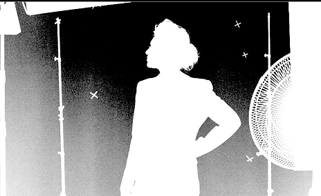
Next up we got the Framehold and kept it on the hero frame which was 200. Then we got a Rotopaint and put it on the top of the Framehold. After this we got a copy node and Roto and put this in the Tree node. next up we put in a Premult put in the Tracker. After all this we will be adding a Merge node and turn the merge into a mask.
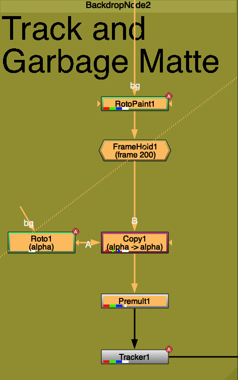
Next we will bring in the CopyNode and connect it to Merge and the other node to the original. under the copy node we added Despill_madness, grade to change the colour so its matches with the background and saturation too. Then in the end we put a Premult and connect it to Merge as an A pipeline and then the B to the constant we created earlier. Below Ive put the final tree node and the Final image sequqnce.
